
Sub-system Diagrams
This section covers the following topics:
- Open-loop control
- Closed-loop control
Overview
Open-loop control
The ‘Universal System Diagram’ is a very basic way for working out how a piece of technology works.
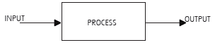
To obtain a greater understanding of the system, though, we have to break it down into more detail. To do this, something called a ‘sub-system diagram’ must be drawn. By using a sub-system diagram, it shows more detail of how a system works. For example, if we consider a hairdryer, a normal system diagram would only show what is going into and out of the system. Not much information can really be learned from this. By breaking it down into the sub-system diagram, it informs us of the internal workings and gives a clearer picture of how the system works.
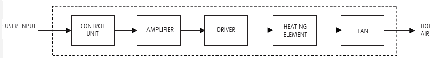
This is the simplest level at which a control system can process an input condition to produce a specified output. It is known as open-loop control.
For more on this topic, have a look at our Higher Engineering Science Study Guide, pp. 8–9.
Related Videos
Watch this video for a greater understanding of closed-loop control.
Quizzes
Click a link below to take a topic quiz:
Thoughts
A street-lighting system is controlled automatically. When the outside light drops below a set level, a lamp comes on.
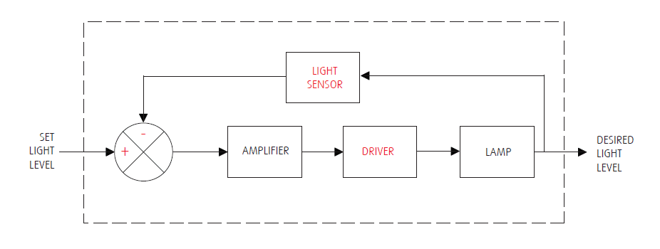
Closed-loop control.
- The system senses the light level that is input into the system.
- The error detector detects whether the actual light level and reference light level differ, and it will generate a signal proportional to this difference.
- The signal is then amplified by the amplifier and fed to an output driver.
- The output driver will increase the power, allowing the lamp to be switched on.
- The lamp switches on.
- A signal is also sent back to the output device, letting it know whether a difference exists between the set light and the reference light level. As long as there is a difference between them, the system will attempt to reduce this difference.